Infrastructure
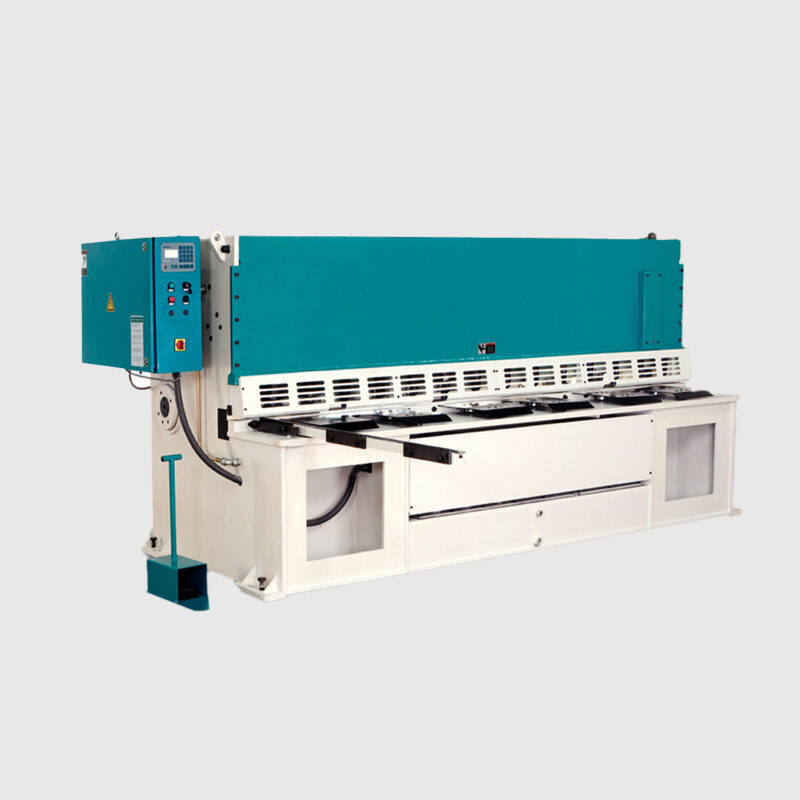
HYDRAULIC SHEARING
MACHINE
A Hydraulic Shearing Machine is an industrial tool used for cutting metal bars and sheets that you otherwise would find difficult to cut. It includes a combination of rotating blades and disks that allow for the above-mentioned action.
Since Hydraulic Shearing Machines all have the same mechanism (more or less), they can be of different kinds based on their blades’ shapes — linear or circular. There are various ways of shaping a given material or metal, of which shearing is a method. Other methods include bending, cutting, spinning, and rolling.
LASER
MACHINE
Advantages of our Fiber Laser Metal Cutting Machine
The high-precision, high-speed and quality of laser cutting has made it the technology of choice for advanced manufacturing across countless industries.
With IPG Fiber lasers source, laser cutting has become a reliable and highly cost-effective solution, resulting in increased adoption throughout the metal manufacturing world.
Benefits of Fiber laser cutting include:
• Precise and repeatable high-quality cuts
• High-speed cutting
• Non-contact cutting - no degradation in cut quality
• Improve your cutting speed and precision
• Minimal maintenance - high tool availability
• Scalable process from micro cutting stents up to shaping structural steel
• Easily automated for maximum productivity
• Easy to cut reflective material.
Fiber laser metal cutting machines have been gradually popularized in metal processing industries.
We believe many laser machine investors have interest in the question that which industries are the mainstream application field of fiber laser cutting machine, so that to develop their laser business better. Below we concluded 9 main applications of fiber laser metal cutting for your reference.
1. Decoration industry
2. Automobile industry
3. Advertising industry
4. Kitchenware industry
5. Lighting industry
6. Sheet metal processing
7. Fitness equipment
8. Home appliance industry
9. Aviation industry
Fiber laser metal cutting machine has the incomparable flexibility and processing precision of the traditional processing method. Because it uses "contactless processing" method that does not need mold making and extra cost Therefore, fiber laser cutting technology can effectively improve product quality, reduce production costs, reduce labor intensity, improve traditional sheet metal processing technology, and bring more benefits to manufacturers.
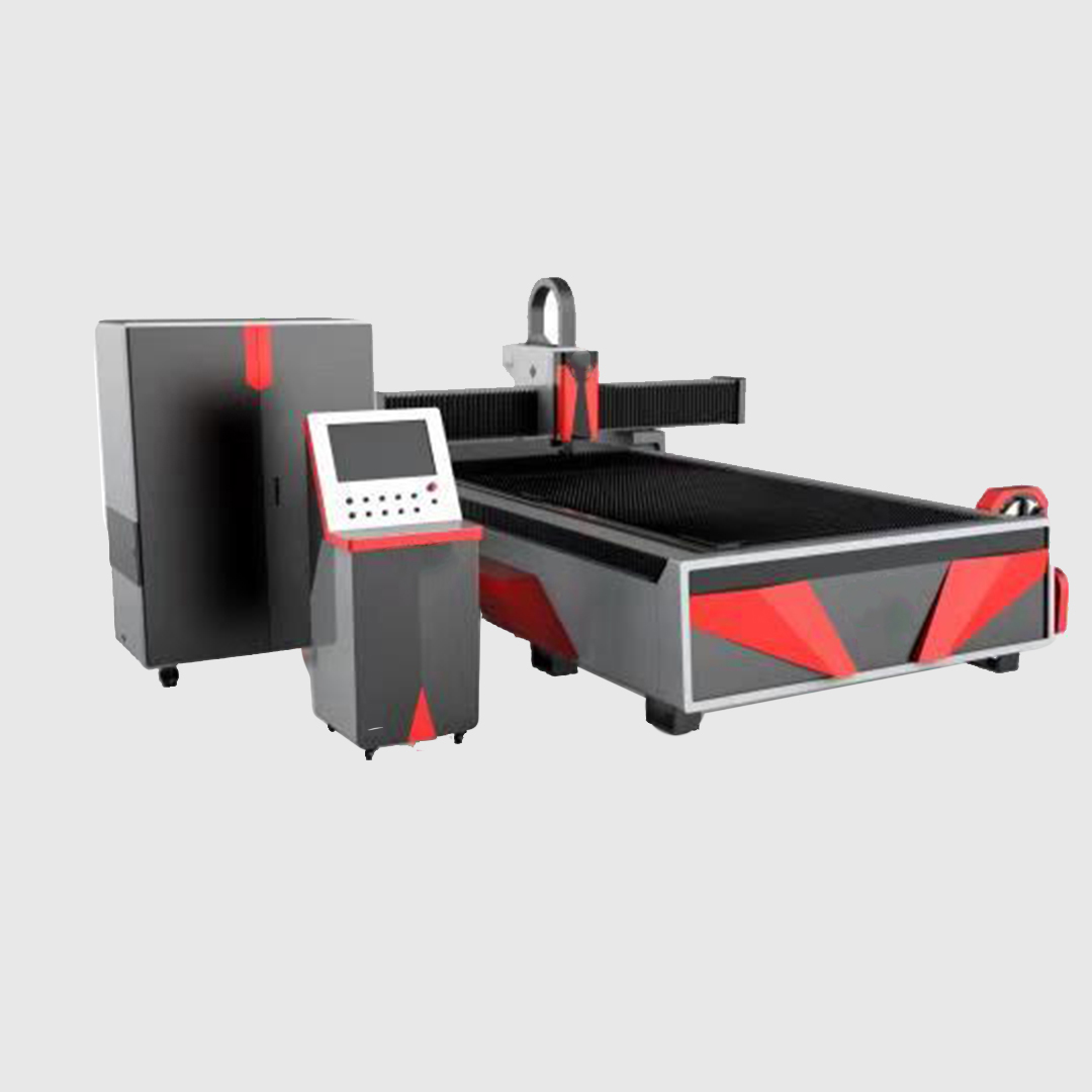
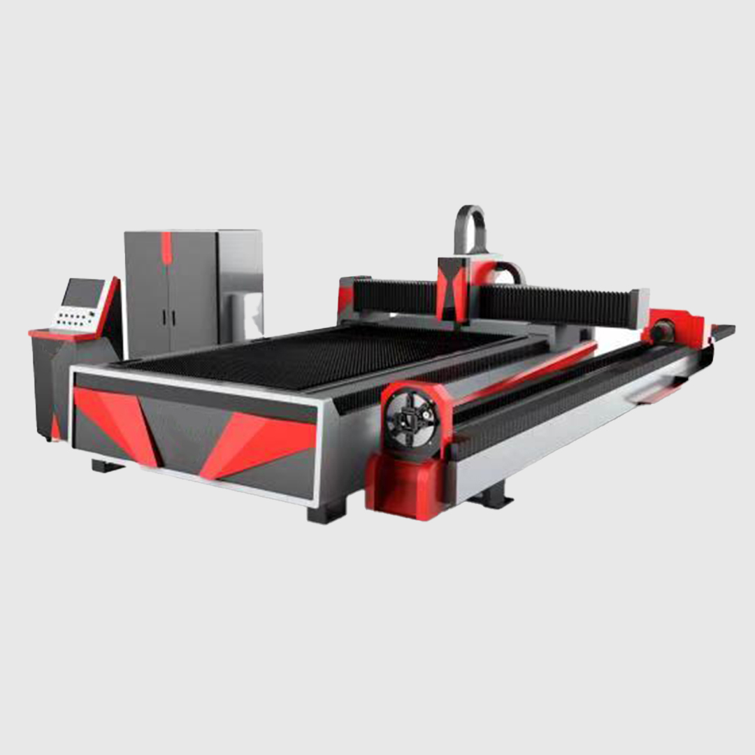
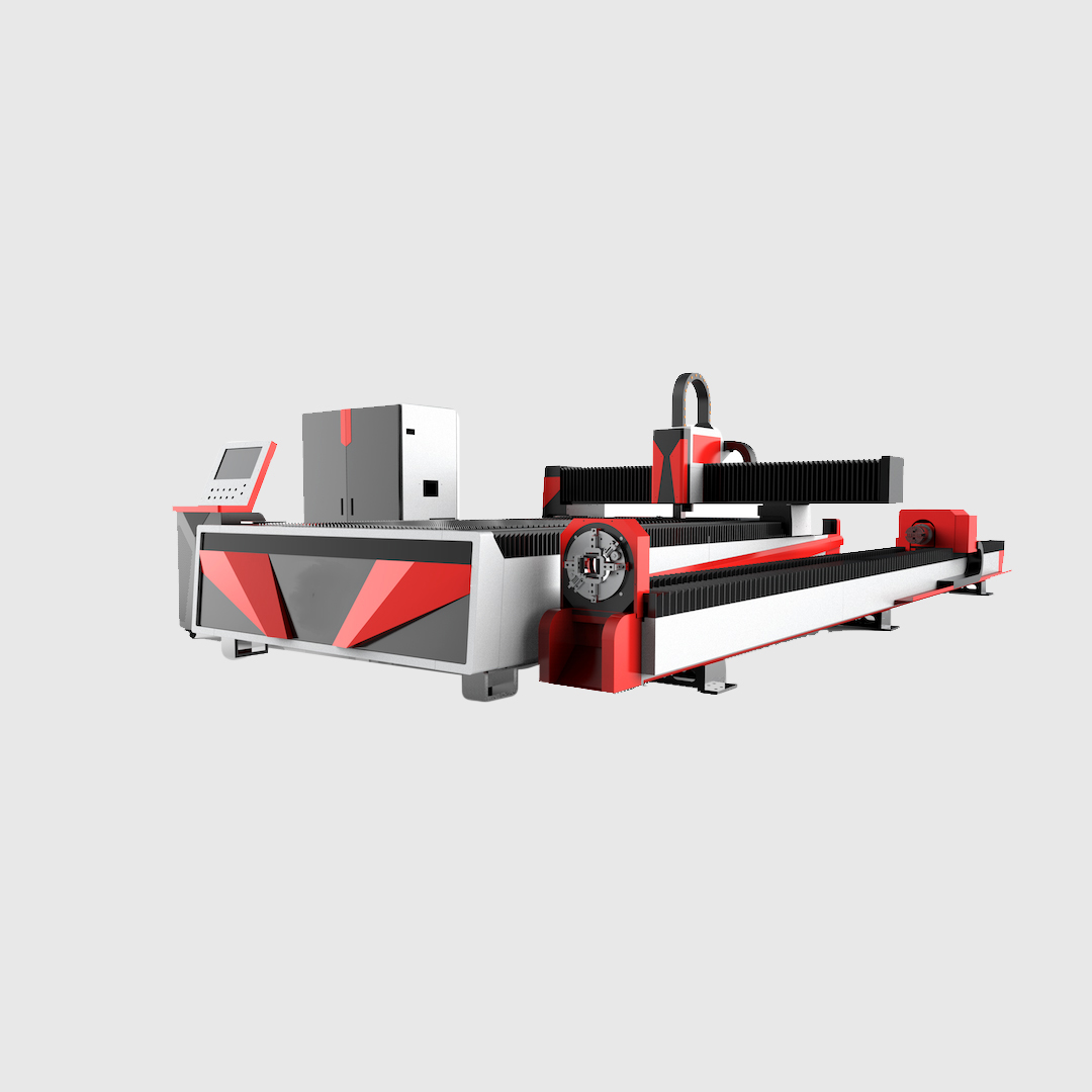

COMING SOON
ROBOTIC LASER
ARM
The Fiber Laser Cutting Robotic Arm is ideally suited to integration and automation for cutting and welding applications. Fiber lasers with laser source power ranging from 700W to 3000W provide manufacturers with dynamic material handling capabilities. These custom-built systems offer increased flexibility, reliability, and quality. Optimum return on investment is guaranteed with these fully programmable machines.
The robotic laser cutting system adopts world class robot from ABB, Fanuc or Staubli integrated with fiber laser source and best of designed cutting head. This machine performs well with its high precision, high efficiency and low noise when running at full capacity.
This 6-Axis laser cutting machine is used in precisely cutting 3D parts with complex surface. Specially suitable for cutting covering parts of automobile and aviation industry, such as edge and hole cutting. It can replace the traditional trimming die and piercing die. It can achieve high-quality, high-precision and high-efficiency cutting of 3D parts without secondary processing.
HYDRAULIC BENDING
MACHINE
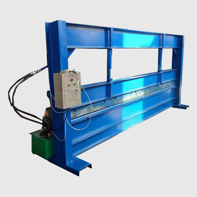
Hydraulic bending machine is generally used in the industry for the bending of plates, and the strength is controlled according to the system parameters to achieve different bending effects. The structure includes a support, a workbench, and a clamping plate. The workbench is placed on the support. The workbench is composed of a base and a pressing plate. The base is connected to the clamping plate through a hinge. The base is composed of a housing, a coil, and a cover plate. The coil is placed In the recess of the seat shell, the top of the recess is covered with a cover plate.


HYDRAULIC COLUMN
PRESS
A hydraulic press is a mechanical device that uses the static pressure of a liquid, as defined by Pascal‘s principle, to shape, deform, and configure various types of metals, plastics, rubber, and wood. The mechanism of a hydraulic press consists of a mainframe, power system, and controls.
COLUMN DRILL
MACHINE
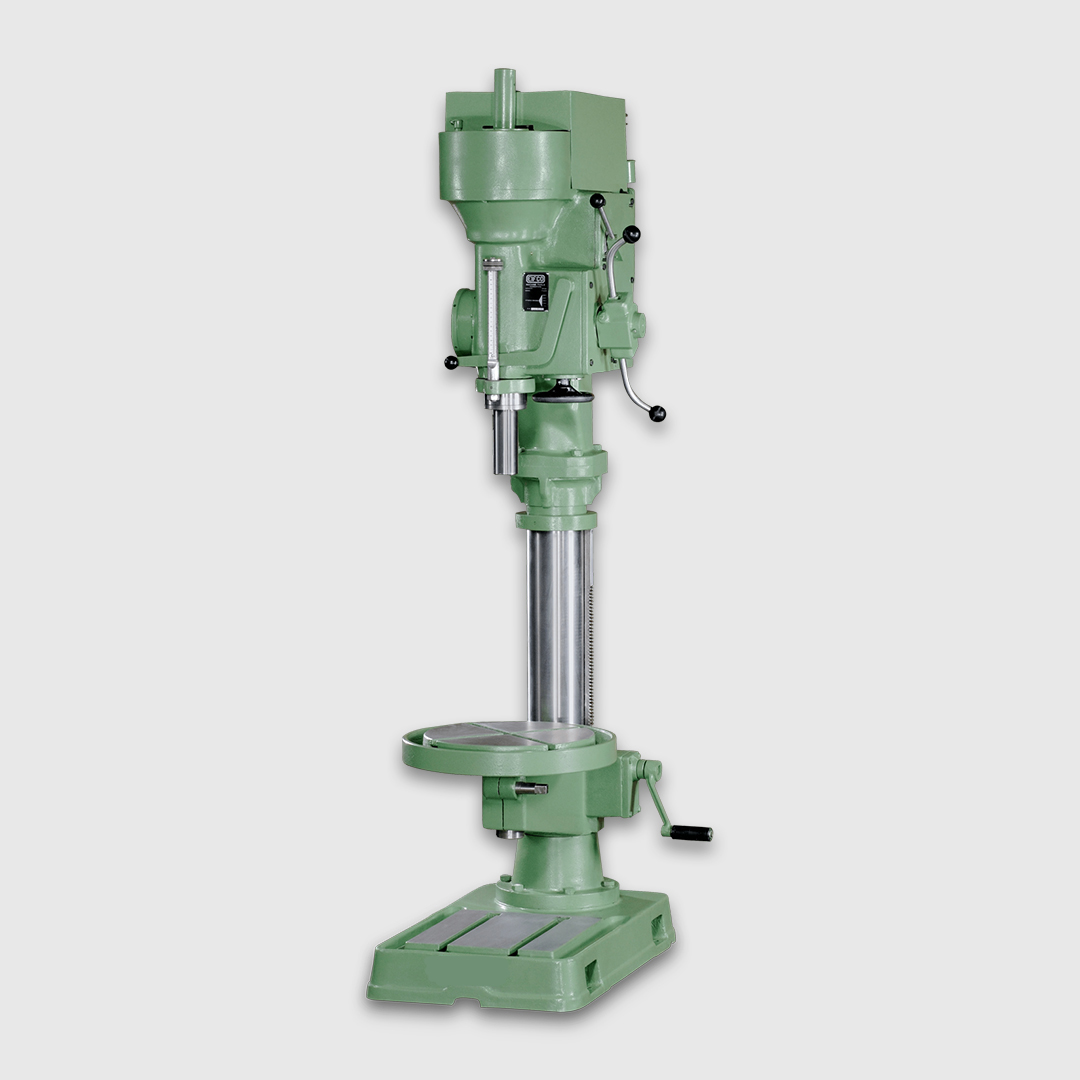
The drilling machine is one of the most important machine tools in a workshop. As regards its importance, it is second only to the lathe. In a drilling machine holes can be drilled quickly and at low cost. The hole is generated by the rotating edges of a cutting tool known as the drill which exerts large force on the work clamped on the table. As the machine tool exerts a vertical pressure to originate a hole it is loosely called a drill press. Drilling machines are made in many types and sizes, each is designed to handle a class of work or specific jobs to the best advantage.

ARC WELDING
MACHINE
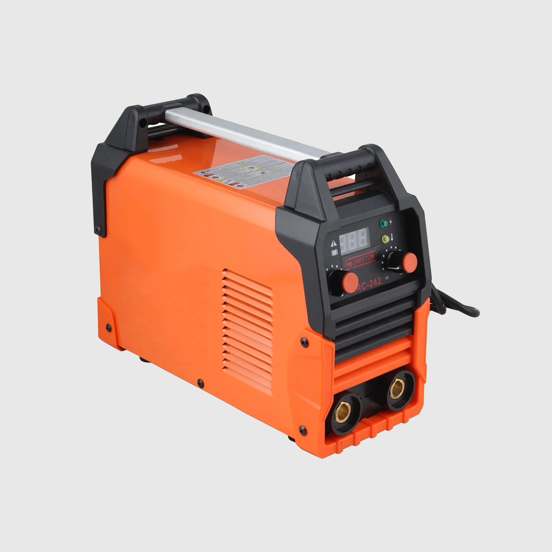
An arc welding machine is a device used for fusing metals. The machine emits an electrical arc from an electrode which melts metal or supplies filler into a joint between two pieces of metal. To produce the temperatures up to 3,600ºC needed to fuse metals, arc welding machines consume significant quantities of energy.
Many arc welding machines sold today use far less energy than older models, even when they are idling. Newer units fitted with inverter power sources are lighter, more versatile and more energy efficient than those powered by older, transformer-rectifier power sources.
SPOT WELDING
MACHINE
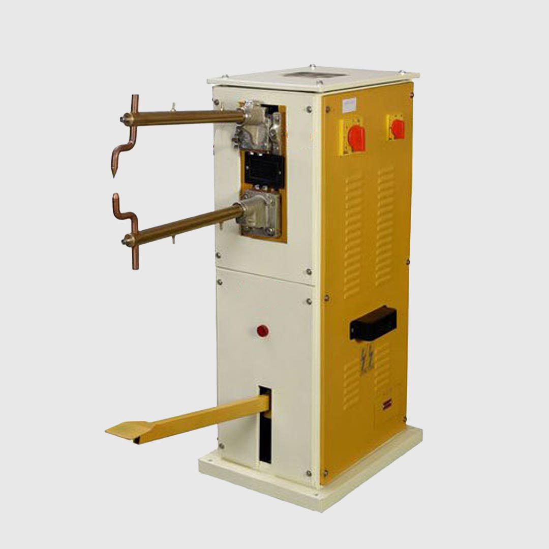
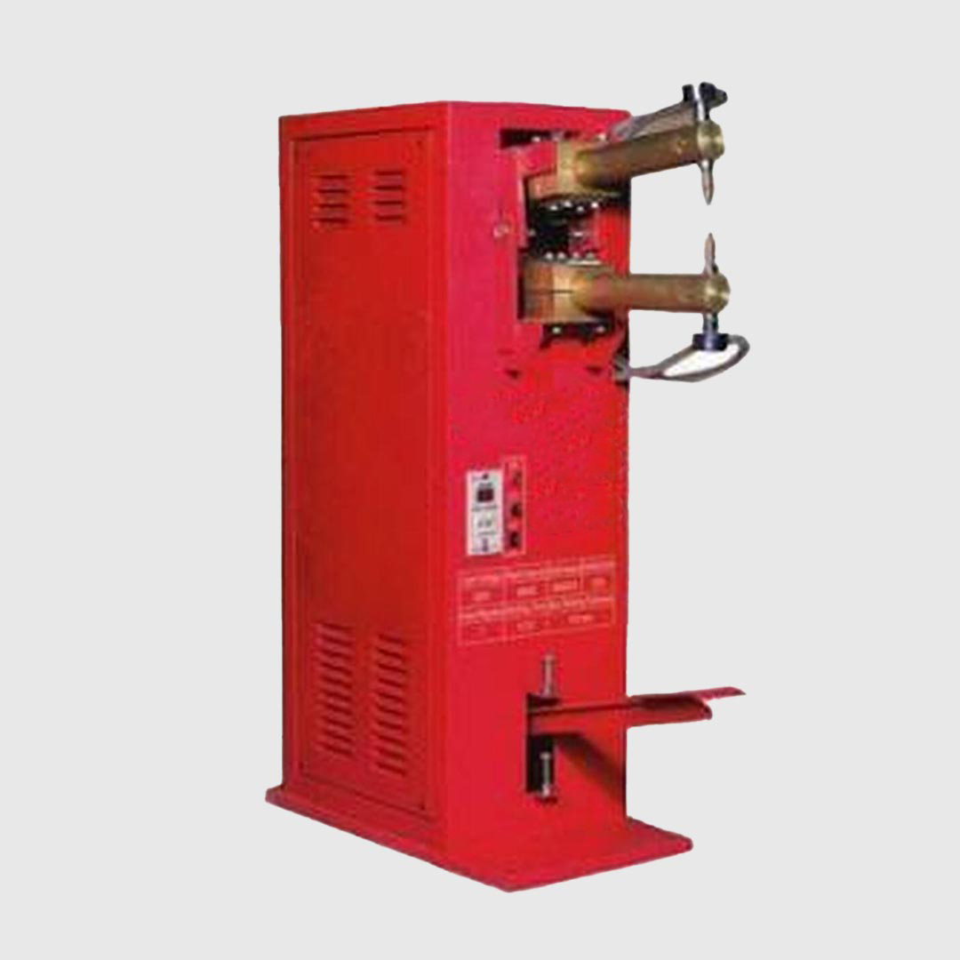
Spot welding (or resistance spot welding[1]) is a type of electric resistance welding used to weld various sheet metal products, through a process in which contacting metal surface points are joined by the heat obtained from resistance to electric current.
The process uses two shaped copper alloy electrodes to concentrate welding current into a small "spot" and to simultaneously clamp the sheets together. Work-pieces are held together under pressure exerted by electrodes. Typically the sheets are in the 0.5 to 3 mm (0.020 to 0.118 in) thickness range. Forcing a large current through the spot will melt the metal and form the weld. The attractive feature of spot welding is that a large amount of energy can be delivered to the spot in a very short time (approximately 10–100 milliseconds).[2] This permits the welding to occur without excessive heating of the remainder of the sheet.
The amount of heat (energy) delivered to the spot is determined by the resistance between the electrodes and the magnitude and duration of the current.[3] The amount of energy is chosen to match the sheet's material properties, its thickness, and type of electrodes. Applying too little energy will not melt the metal or will make a poor weld. Applying too much energy will melt too much metal, eject molten material, and make a hole rather than a weld.[4] Another feature of spot welding is that the energy delivered to the spot can be controlled to produce reliable welds.

MANUAL POWDER
COATING SETUP
The powder-coat process cosists of the application of electrostatically charged particles onto the surface of the material to be coated. In a typical powder-coating system, a feeder unit delivers the powder to an electrostatic gun. The feeder unit also controls the flow of powder to the gun. The gun emits the powder in the form of a diffused cloud. When combined with an electrical field charge provided by a low-amperage power unit, the charged particles seek out and adhere to the surface of the material.
POWDER COATING
BOOTH
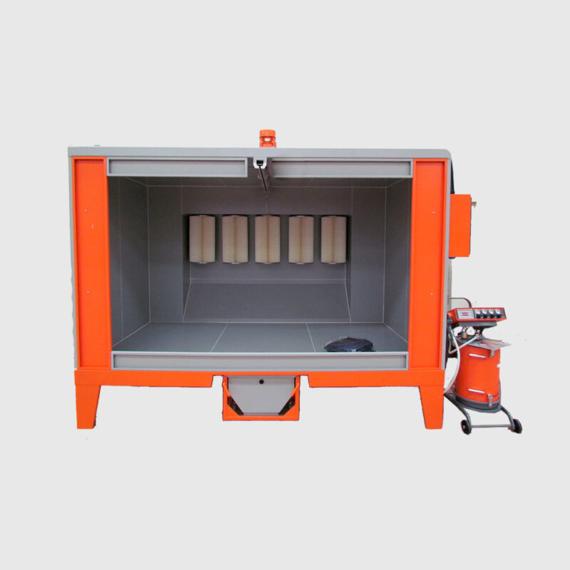
Powder Booth - Powder Booth is a chamber or a cabin where the powder ( pigment of different colors ) are been sprayed by means of a powder gun on the component to be powder coated. These Chambers are built out of MS sheet metal or SS sheet metal. The powder coating booth is divided into two sections namely The powder spraying area and the powder recovery area.
POWDER COATING
OVEN
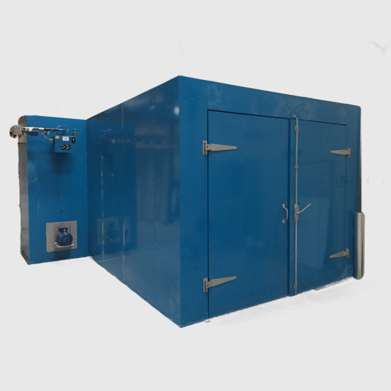
Upon application of the coating, the next step in the powder-coating process is curing, which involves baking the workpiece in a specially designed oven. Curing results in the formation of a protective skin and promotes coating adhesion. In general, curing is performed at 400 F for approximately 20-30 minutes, although these parameters can vary based on the type of powder coating.
Surface preparation/pretreatment is also essential for achieving a successful powder-coating outcome. This normally entails the removal of grease, oil, dirt and other materials via chemical, physical or mechanical methods to clean the surface and promote coating adhesion. Pretreating the workpiece with chemical compounds can enhance the coating’s performance, durability and corrosion resistance.
